


 English
 русский
 عربى
عربى
Cat:CNC Roll Milling Machine
CNC Notching and Marking Machine
XK9350 series CNC rebar roll crescent groove milling machine is the upgraded product of XK500 type, which is suitable for processing rolls with diamet...
See DetailsThe large-scale production of steel shaping rolls, paper calendar cylinders, and industrial crushing drums requires structural machinery built to process immense masses while achieving exceptional geometrical accuracy. A CNC roll turning lathe delivers this exact balance of power and precision by utilizing heavy cast beds, ultra-high-torque headstocks, and closed-loop computer control to reshape workpieces made from hardened alloys, high-chromium steel, or chilled cast iron. By automating the turning of large external cylindrical profiles, tapering zones, and complex pass grooves, these robust machine tools eliminate human error, slash production times, and optimize surface finishes across intense metalworking applications.
To turn a workpiece roll that frequently weighs between 5 and 50 metric tons, the foundational frame of a CNC roll turning lathe must be engineered with massive structural stiffness. Unlike lighter manufacturing lathes, a roll turning machine utilizes a wide, flat, multi-guideway bed design molded from premium grey cast iron or mineral composite materials. This wide configuration distributes the heavy downward gravitational force of the roll across a broad footprint, preventing localized sagging or deflection along the longitudinal travel path.
The mechanical arrangement usually includes a heavy headstock driven by a multi-stage gearbox or high-torque synchronous motor, forming the primary spindle axis. The opposite end of the heavy workpiece is supported by an over-engineered tailstock body that slides along the guideways using dedicated racking gears. To prevent the heavy cylinder from sagging under its own weight in the middle section, adjustable hydraulic or mechanical steady rests are mounted along the bed tracks, providing essential upward support to preserve geometric concentricity during cutting operations.
The type of guideway system determines how well the lathe carriage handles heavy loads and controls friction during operation:
Maintaining tight tolerances across an extended roll profile presents significant challenges, particularly when coping with internal mechanical backlashes and thermal expansion. As the cutting tool carves through high-hardness metals, the intense friction generates high temperatures that gradually heat up the lathe's lead screws and cast structure, causing subtle dimensional shifts.
To counteract this thermal movement, a professional CNC roll turning lathe relies on a dual-axis closed-loop feedback design. Rather than inferring tool position from motor rotation data, the machine utilizes absolute linear glass encoders mounted directly along the longitudinal (Z-axis) and cross-feed (X-axis) tracks. These glass scales continually read the true physical position of the cutting tool carriage relative to the workpiece, sending instantaneous data adjustments to the CNC processor. If the system detects a deviation as minute as 3 microns due to structural expansion, it immediately compensates by adjusting the servo positioning, ensuring flawless dimensional precision.
Because industrial rolls are manufactured from tough, wear-resistant alloys, the lathe headstock must focus heavily on low-speed torque over high-speed rotation. These specialized spindles feature multi-tier internal planetary gear sets that deliver massive torque at rotational speeds often dropping below 10 RPM. This controlled force allows the lathe to slice through tough outer metal shells without stalling the drive motors or inducing tool chatter.
Varying industries require vastly different roll dimensions and material configurations. A metal rebar reduction roll requires deep, high-traction pass profiles, while a high-speed paper calendar cylinder demands a flawlessly smooth, mirror-polished outer surface.
The table below outlines common machining benchmarks, target accuracies, and tool selections across several major industrial roll turning applications:
| Roll Industry & Application | Typical Workpiece Metallurgy | Average Hardness Limit | Target Dimensional Tolerance | Optimal Cutting Tool Composition |
|---|---|---|---|---|
| Hot Section Steel Rolling Mill | High-Chromium Forged Steel | 65 - 72 HRC | ±0.015 mm | Polycrystalline Cubic Boron Nitride (PCBN) |
| Industrial Paper Calendar Press | Chilled Double-Pour Iron Alloy | 520 - 580 HB | ±0.005 mm | Silicon Nitride (Si3N4) Ceramic Inserts |
| Mining Mineral Crushing Drum | Austenitic Manganese Steel | 220 - 260 HB | ±0.030 mm | Heavy-feed PVD TiAlN Coated Carbide |
| Rubber Cladding Backing Roll | Medium Carbon Structural Steel | 320 - 360 HB | ±0.010 mm | Multi-layer CVD Coated Carbide Inserts |
Turning highly alloyed industrial cylinders generates significant thermal energy right at the cutting point. Because the lathe tip remains in continuous contact with the turning metal surface for long periods, managing heat dissipation and controlling the resulting chip ribbon are vital factors in tool longevity.
To protect the tool, modern machining strategies use specialized chip breakers combined with high-pressure, through-tool coolant systems pressurized to at least 30 bar (435 psi). This targeted coolant jet quickly breaks up what would otherwise be long, dangerous ribbons of hot steel into small, manageable chips, washing them away from the cutting zone. Striking the right balance keeps the tool edge intact and avoids surface scratching on the freshly turned roll profile.
When machining materials harder than 60 HRC, standard sharp tool edges will chip or shatter almost instantly under the intense forces. Instead, technicians select heavy-duty inserts designed with negative rake angles and wide, micro-honed edge radii. This design geometry distributes the initial impact shock across a larger portion of the carbide substrate, utilizing the material's compressive strength to safely absorb the immense cutting pressures.
Because a CNC roll turning lathe operates under continuous heavy loads, keeping its components in peak working order requires a rigorous and structured preventive maintenance routine.
An excellent way to maximize operational efficiency on a CNC roll turning lathe is to integrate automated, in-process measurement probes directly into the tool turret. Manually removing a multi-ton cylinder from the lathe bed to check its dimensions on a remote coordinate measuring machine (CMM) consumes valuable shop time and introduces serious alignment risks when trying to reload the part back onto the machine centers.
Modern setups use radio-frequency or optical touch-trigger measurement probes that deploy automatically between roughing and finishing passes. The probe scans key diameters along the length of the roll, transferring real-time measurements back to the CNC system. The software automatically compares these readings against the target blueprints. If it detects slight variances caused by tool wear, it immediately updates the tool offsets and executes a precise finishing cut. This integrated double-check ensures the completed roll matches specifications before it ever leaves the lathe centers.
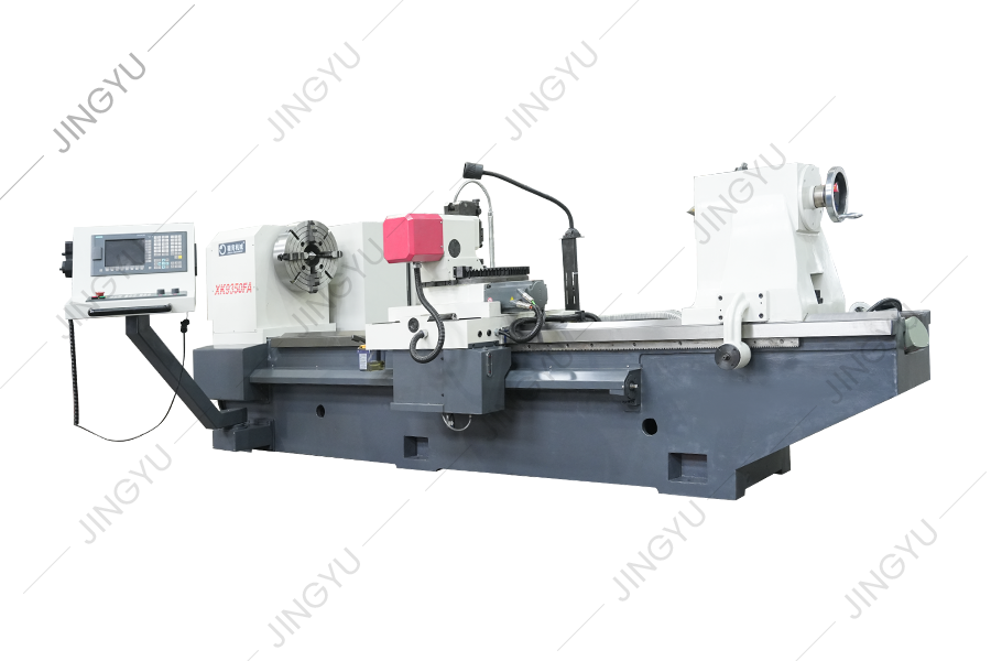
XK9350 series CNC rebar roll crescent groove milling machine is the upgraded product of XK500 type, which is suitable for processing rolls with diamet...
See Details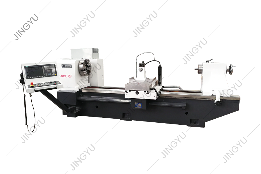
XK9350 series CNC rebar roll crescent groove milling machine is the upgraded product of XK500 type, which is suitable for processing rolls with diamet...
See Details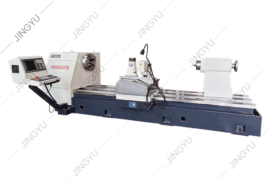
This series of machine tools can automatically cut crescent grooves with different rotation directions and any helix angle. It can divide into equal (...
See Details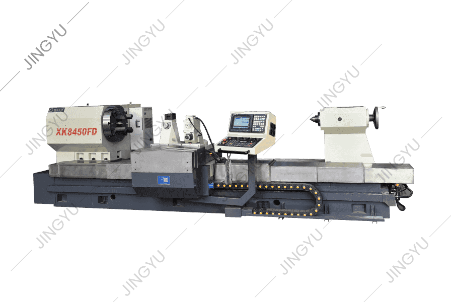
In view of the problems of high speed steel roll processing, XK8450 CNC roll milling machine is a new type of CNC roll groove processing machine tool ...
See Details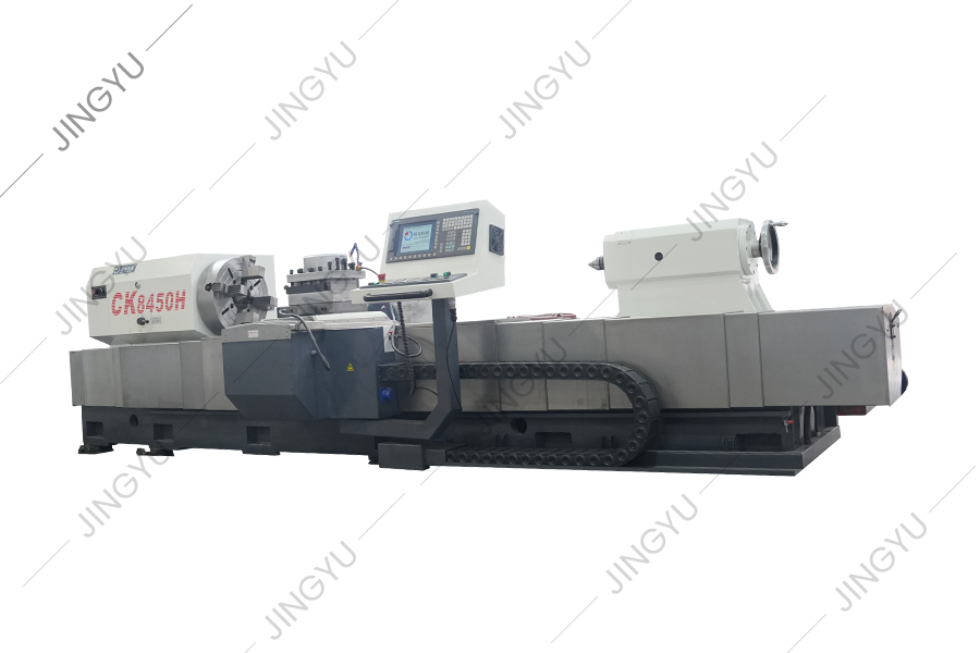
This series of machine tools is mainly used to pass and process rolls. It can also turn the outer circle and roll neck of rolls, and can also turn par...
See Details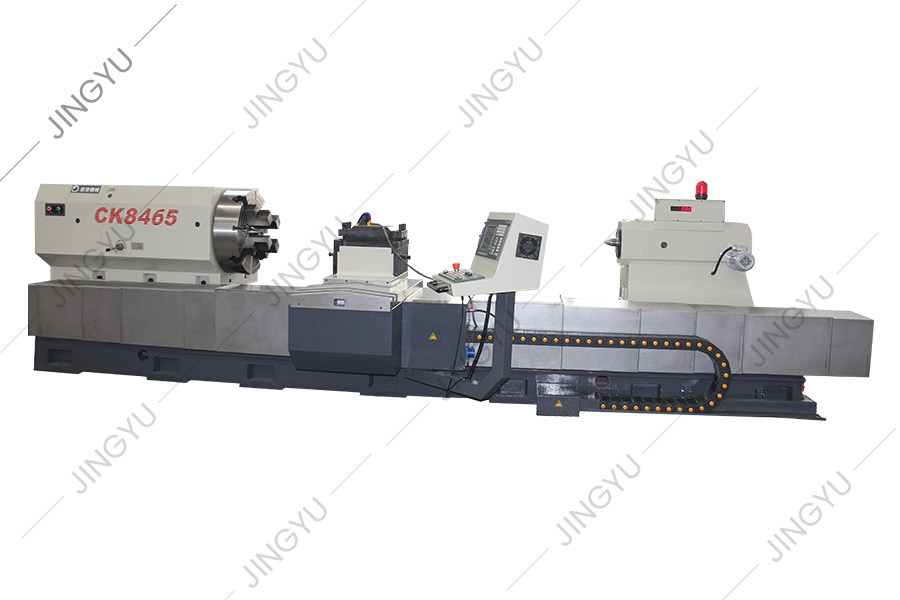
CK8465H CNC roll lathe bed adopts a 2+3 heavy-duty linear rolling guide structure, that is, two rectangular guide rails arranged horizontally on the b...
See Details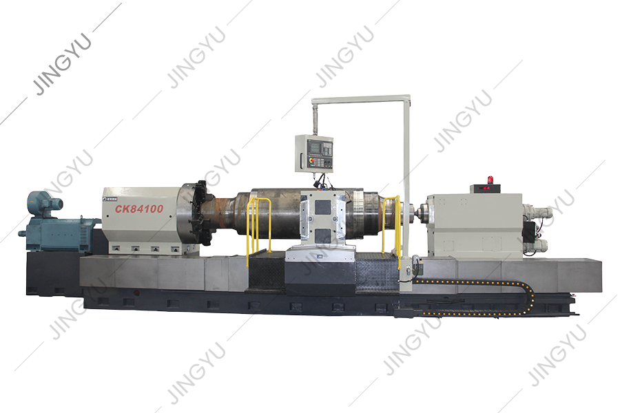
CK84 series CNC roll lathe adopts Siemens 828D CNC system and is driven by a servo motor. When designing this machine tool, we fully analyzed the tech...
See Details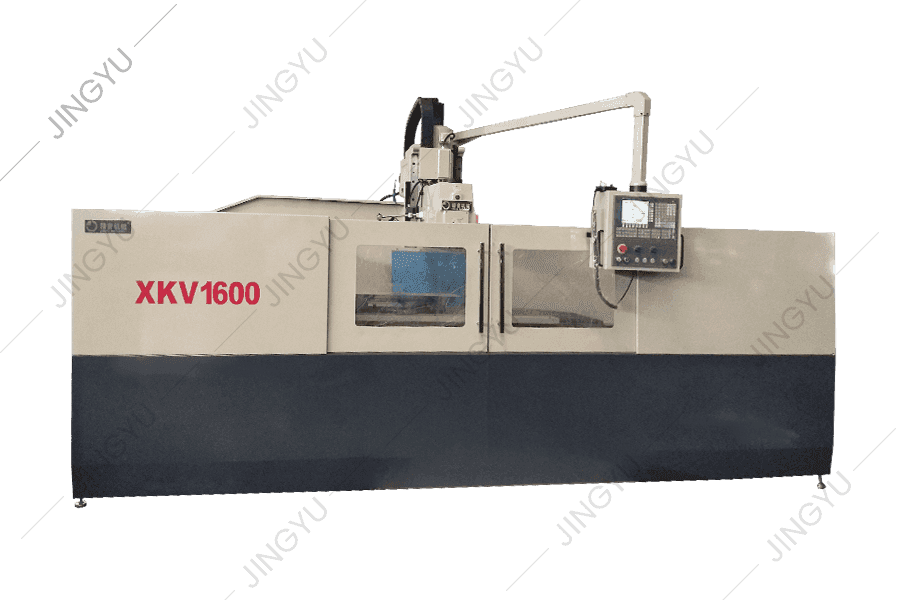
The CNC-reinforced milling machine adopts a full-gear spindle box, and the spindle transmission part adopts gears with precision of more than 6 levels...
See Details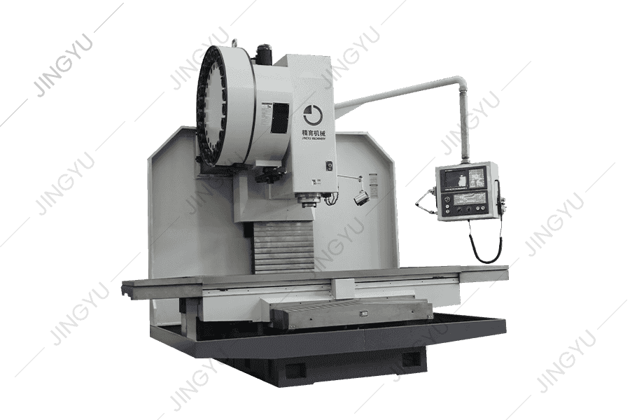
All three axes of the machine are P3-level 50×P10 ball screws, and the assembly process of 2-end fixed pretension is used to strengthen the axial rigi...
See Details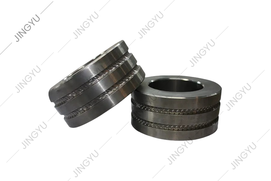
This series mainly provides common-wearing parts for CNC TC ring grinding machines and composite roll grinding machines, such as mandrels, dynamic and...
See DetailsNo.3, Xinghe Road, Zhaxi Industrial Park, Chongchuan District, Nantong, Jiangsu Province, 226003, P.R.China
info@rolllathe.com jennifergao@rolllathe.com
+86-513-85636116
Copyright © Nantong Jingyu Machinery Co., Ltd. All Rights Reserved
 China Roll Turning Lathe Manufacturers
