


 English
 русский
 عربى
عربى
Cat:CNC Roll Milling Machine
CNC Roll Milling Machine
This series of machine tools can automatically cut crescent grooves with different rotation directions and any helix angle. It can divide into equal (...
See DetailsThe manufacturing of heavy-duty section mill rolls, rebar profiling rolls, and corrugated crushing cylinders requires geometric tolerances and surface finishes that traditional manual machining cannot achieve. A CNC roll milling machine solves this precision challenge by combining rigid, heavy-duty mechanical beds with multi-axis computer numerical control (CNC) interpolation to cut complex grooves, notches, and ribs into hardened steel or chilled cast iron roll bodies. By automating tool-path generation and controlling cutting forces, these advanced machine tools eliminate human error, optimize production efficiency, and guarantee the absolute repeatability of profile dimensions across long manufacturing campaigns.
To machine workpiece rolls that can weigh anywhere from several hundred kilograms to upward of thirty metric tons, the physical frame of a CNC roll milling machine must possess immense static and dynamic rigidity. The base structure typically relies on a heavily ribbed, single-piece grey cast iron or composite mineral bed design, engineered specifically to damp out high-frequency harmonic vibrations generated during heavy interrupted cutting processes.
The operational layout utilizes a split-axis kinematic design. The workpiece roll is secured between a robust, high-torque headstock spindle and a heavy-duty hydraulic tailstock assembly, defining the rotational axis. The milling cutter head is mounted to a separate traveling saddle assembly that moves parallel and perpendicular to the workpiece body.
Achieving intricate profiles, such as the crescent-shaped deformations required on steel reinforcing bars (rebar), demands continuous coordination between multiple machine axes:
When cutting spiral or helical patterns, the CNC system uses simultaneous three-axis electronic interpolation to link the linear travel of the Z and X axes with the rotary positioning of the C axis, ensuring uniform groove distribution across the entire cylinder circumference.
Thermal expansion and mechanical backlash represent major hurdles when striving for sub-micron accuracy in heavy machining environments. As a CNC roll milling machine operates over an extended multi-hour shift, friction within the ball screws and guide ways generates heat, causing components to expand slightly.
To mitigate this structural distortion, advanced roll milling platforms implement a strict closed-loop position feedback loop. Instead of relying purely on rotational data from the servo motor couplers, the machine beds are fitted with high-precision absolute linear glass scales. These scales measure the exact physical location of the tool carriage relative to the workpiece, sending real-time position updates back to the CNC processor. If a deviation as tiny as 2 microns occurs due to thermal growth, the control system instantly shifts the servo drive commands to correct the error, maintaining strict part dimensions.
Because roll materials are deliberately alloyed for extreme wear resistance, the milling spindle must prioritize raw torque over raw speed. These heads feature integrated multi-stage planetary gearboxes or high-torque synchronous built-in motors capable of delivering immense cutting power at low rotational speeds, often operating below 500 RPM while pushing indexable carbide or ceramic inserts through hardened steel matrices.
Different steel and metal shaping industries require vastly different roll sizes and alloy compositions. A flour milling cylinder, for instance, requires fine, high-density corrugations, whereas a structural steel rolling pass demands deep, wide profiles capable of shaping glowing steel beams.
The table below provides a detailed look at typical machining benchmarks and operational parameters encountered across different industrial roll manufacturing applications:
| Workpiece Roll Application | Common Material Composition | Typical Material Hardness | Target Profile Accuracy | Optimal Cutter Tooling Class |
|---|---|---|---|---|
| Steel Rebar Profiling Rolls | Tungsten Carbide / High-Cr Iron | 75 - 85 HRA | ±0.010 mm | Super-hard diamond-coated solid carbide |
| Agricultural Flour Fluting Rolls | Chilled Double-Pour Cast Iron | 500 - 550 HB | ±0.005 mm | Cubic Boron Nitride (CBN) Inserts |
| Heavy Section Steel Pass Rolls | Forged Semi-Steel Alloy | 300 - 400 HB | ±0.025 mm | Indexable heavy-feed carbide inserts |
| Paper Calendar Pressure Rolls | Micro-Alloyed Forged Steeled | 60 - 62 HRC | ±0.003 mm | Silicon Nitride ceramic inserts |
Milling grooves into extremely hard materials subjects the cutting edge of the tool to intense thermo-mechanical shock. Because the tool enters and exits the metal surface thousands of times per minute during interrupted cutting, managing heat buildup is a vital part of the process.
To prevent premature tool failure, modern CNC roll milling strategies utilize dry machining combined with high-pressure air blasters, or high-volume through-spindle flood coolant systems pressurized to a minimum of 20 bar (290 psi). This high-pressure fluid serves a dual purpose: it instantly cools the cutting zone and clears chips away from the tool path. If chips are left in the groove, the cutter can re-cut them, which quickly chips the carbide inserts and ruins the surface finish of the roll.
When programming tool movements, programmers almost exclusively specify climb milling paths. This approach ensures the cutter insert starts with a thick chip load and thins out as it exits the metal, transferring the cutting heat into the chip rather than the tool insert. This preserves the tool's cutting edge and keeps the machine running longer before needing a tool change.
Because a CNC roll milling machine operates under high loads and handles heavy parts, keeping it in peak condition requires a structured preventive maintenance routine.
An excellent way to improve efficiency on a CNC roll milling machine is to use integrated, in-process measurement probes. Manually taking a large roll out of the machine to check its dimensions on an external coordinate measuring machine (CMM) is time-consuming and introduces alignment risks when reloading the part.
Modern setups use optical or radio-frequency touch-trigger probes loaded directly into the milling spindle head. Once a roughing path is complete, the CNC program pauses to let the probe measure key dimensions along the roll profile. The control system compares these real-time measurements with the original CAD model. If it detects left-over material from tool wear, the system automatically adjusts tool offsets and programs a precise finishing pass. This automated double-check guarantees the roll is perfect before it ever leaves the machine bed.
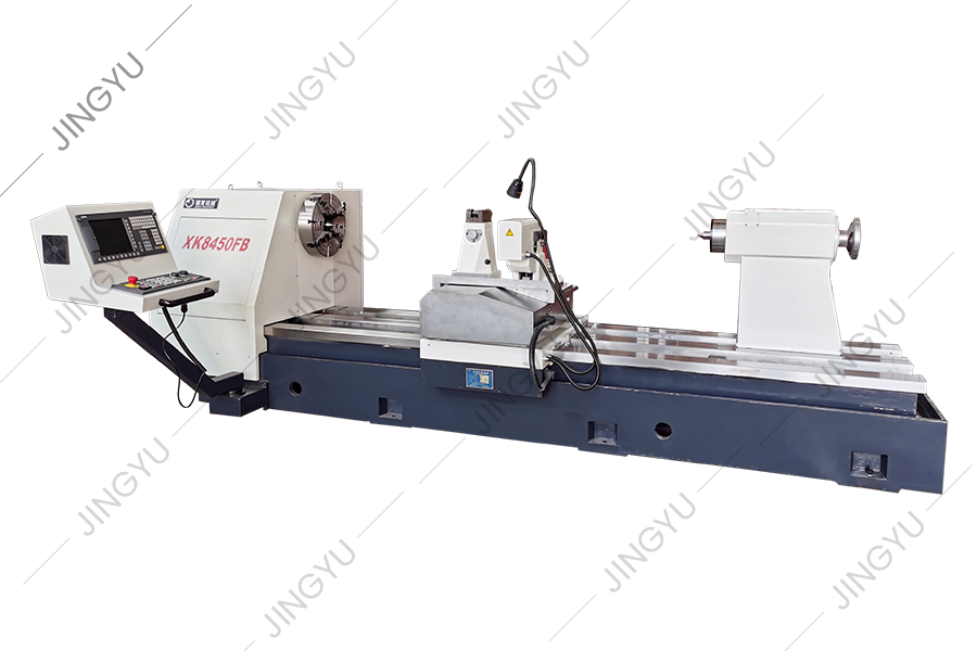
This series of machine tools can automatically cut crescent grooves with different rotation directions and any helix angle. It can divide into equal (...
See Details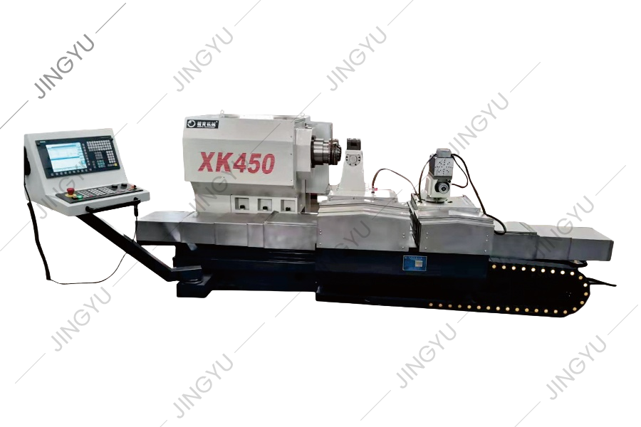
We have accumulated rich experience in the processing and use of rebar rolls, and have conducted in-depth analysis and research on the technology of s...
See Details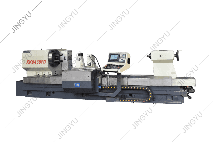
In view of the problems of high speed steel roll processing, XK8450 CNC roll milling machine is a new type of CNC roll groove processing machine tool ...
See Details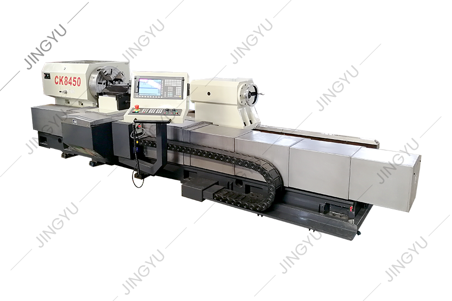
This series of machine tools is mainly used to pass and process rolls. It can also turn the outer circle and roll neck of rolls, and can also turn par...
See Details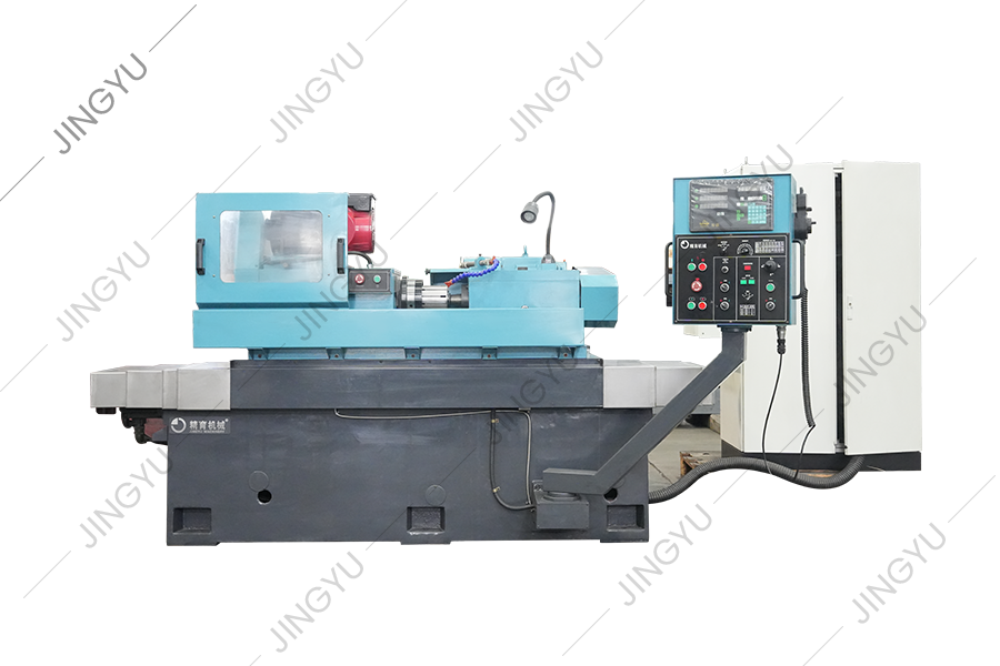
The roll ring forming grinder is mainly used for grinding tungsten carbide roller rings for high-speed wire rod production. The formed diamond grindin...
See Details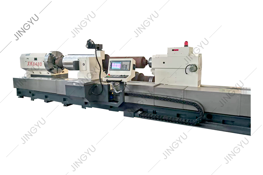
At present, pattern roll engraving at home and abroad generally adopts electrolysis method, ordinary horizontal milling machine milling and other proc...
See Details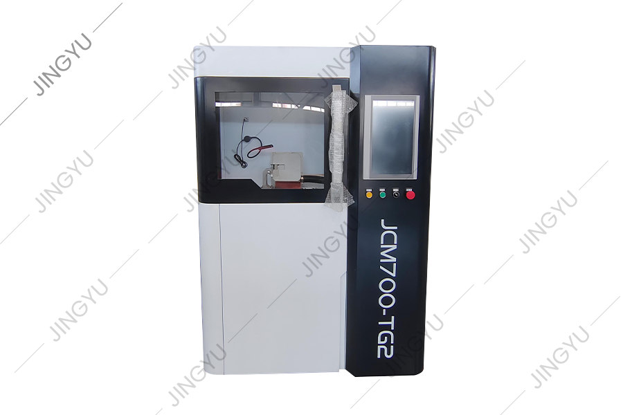
This machine is mainly used for grinding and repairing the milling cutter of roll threaded cross rib, which can easily repair and grind the edge of re...
See Details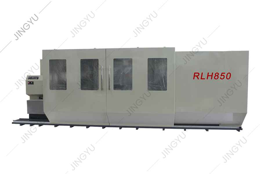
This machine tool is a new type of CNC roll grooving machine tool developed based on the company's CNC roll milling machine series and after full rese...
See Details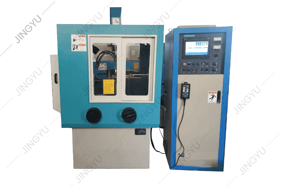
MX250 is a standard diamond wheel dressing machine, used for forming and dressing diamond wheels for metallurgical steel mills. The diameter of diamon...
See Details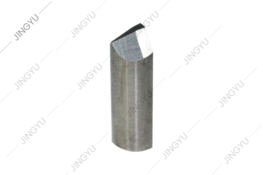
This series is mainly for CNC crescent groove milling machines to provide common-wearing parts, such as milling tool holders, milling cutters, support...
See DetailsNo.3, Xinghe Road, Zhaxi Industrial Park, Chongchuan District, Nantong, Jiangsu Province, 226003, P.R.China
info@rolllathe.com jennifergao@rolllathe.com
+86-513-85636116
Copyright © Nantong Jingyu Machinery Co., Ltd. All Rights Reserved
 China Roll Turning Lathe Manufacturers
