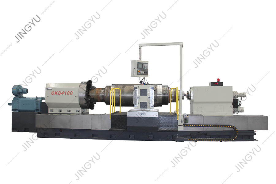
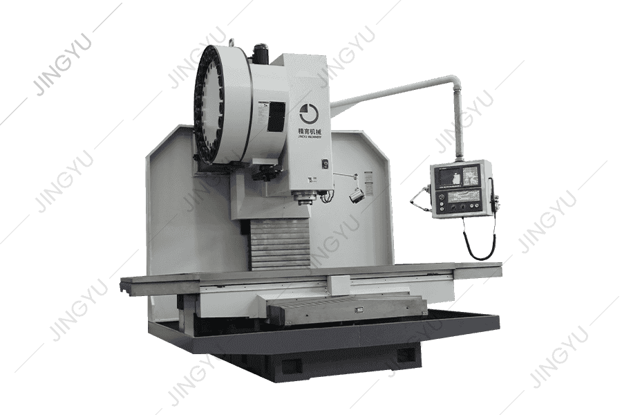
CK84100
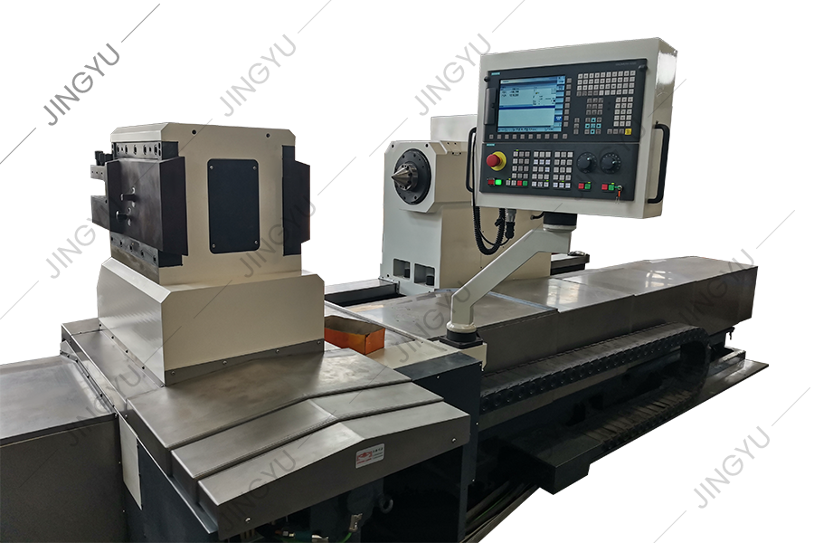
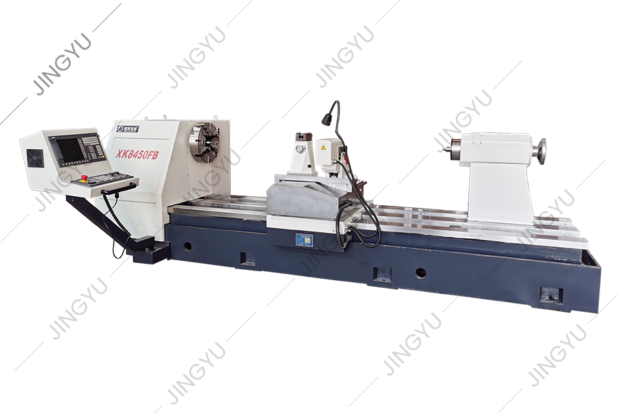
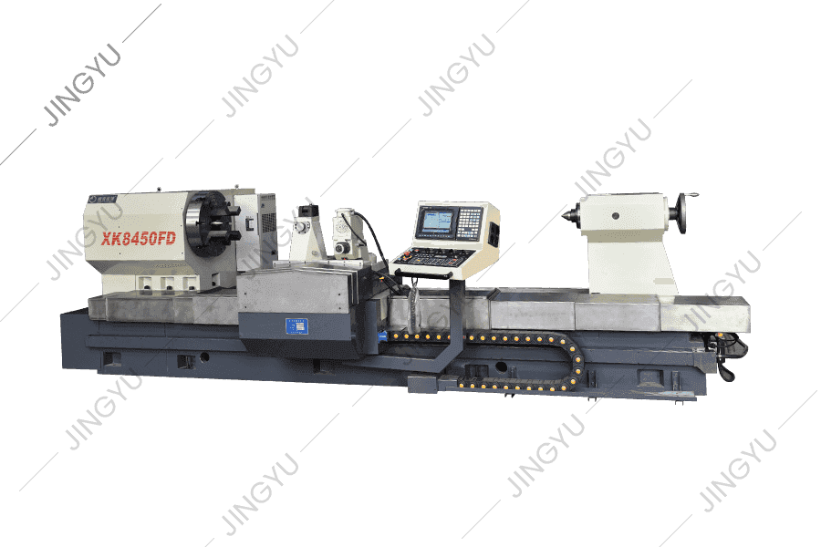
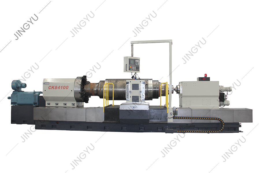
●The CK84100 CNC roll lathe bed adopts the overall 4+1 guide rail structure, that is, the bed's horizontal arrangement of four rectangular rails to provide the movement and positioning of the saddle and tailstock, and set up an auxiliary rail on the vertical surface of the front side of the bed for the saddle auxiliary support, so as to ensure that the saddle, the tool holder has a better rigidity, and can bear a greater cutting torque.
The reference guide rail of the bed adopts the overall super-audio quenching, and the matching surface is affixed with an imported guideway soft belt to ensure the micro-wear movement of each feed component, and maintain high precision and high stability for a long time. A certain height difference is designed between the saddle rail and the tailstock rail to ensure that chips and coolant do not invade the saddle rail.
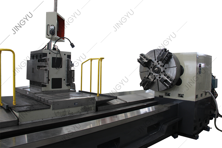
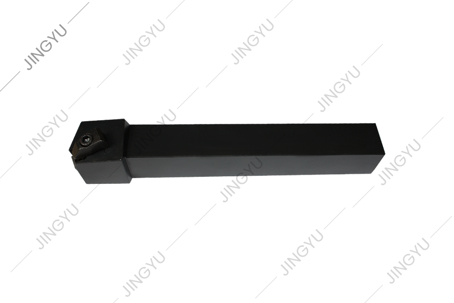
●The saddle tool holder adopts an AO-type integral tool holder scheme. The tool holder can improve the rigidity of the tool holder and reduce the vibration during the turning of the machine tool. And by adjusting the position of the tool rest plate to adapt to the deep groove pass roll processing. Reduce the lack of rigidity caused by the extension of the tool handle, so that the tool handle resonance, affecting the cutting performance.
Our company can also choose to configure the CNC tool holder according to the customer's requirements (it is recommended that angle steel users choose).
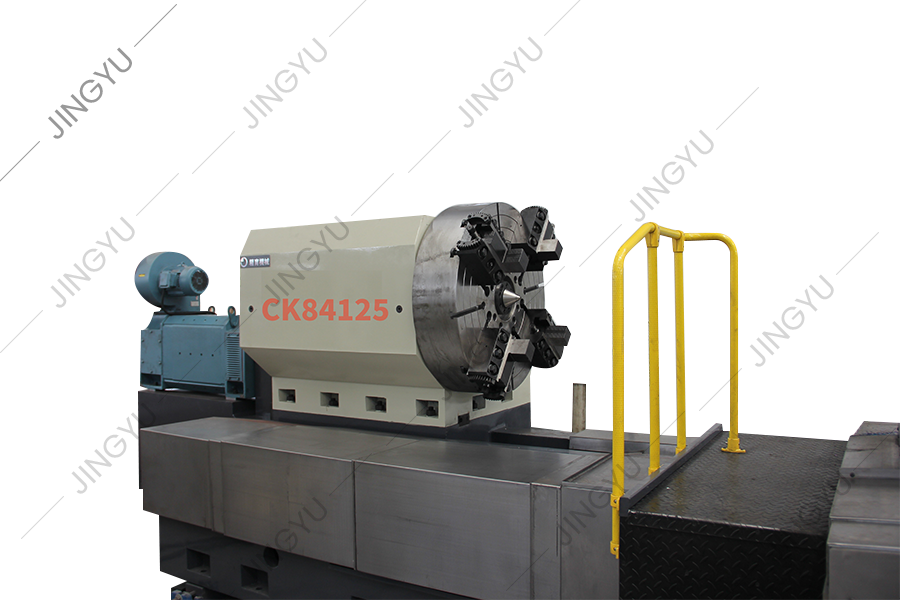
CK84125
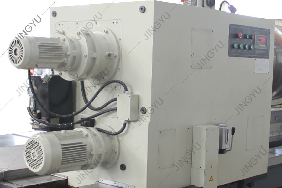
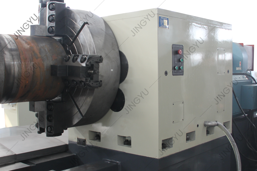
●The lathe headstock adopts a reinforced double-wall box structure; The main shaft adopts the form of two-point support, reasonable bearing configuration, and span design, the main shaft has high rigidity and bearing capacity. The optimized transmission system is all driven by 6-level precision gear with high frequency quenching and grinding so that the headstock has the characteristics of low noise, high transmission accuracy, and large output torque.
The main shaft transmission adopts the hydraulic automatic shift 2 gear shift & DC speed regulation motor drive stepless speed regulation scheme so that the machine spindle has a wide range of 1-200rpm, high dynamic characteristics of the speed regulation range.
The back of the headstock is designed with a button station, which can control the operation of the spindle, such as positive and negative rotation and emergency stop.
●The tailstock adopts a structural plan of independent rotating spindle & axial telescopic adjustment of the tailstock sleeve. The tailstock spindle taper hole is 100-1:5. The tailstock body adopts an integral structure, which eliminates the disadvantages of unstable accuracy, poor load-bearing capacity, and poor reliability caused by the traditional upper and lower split structures.
The tailstock of the machine tool is equipped with a high-performance pressure sensor, which is used for the setting, measurement, and feedback of the tailstock clamping force when the lathe clamps the workpiece. By setting and adjusting the operating pressure sensing controller, the tightening force of the tailstock tip on the workpiece can be automatically controlled and displayed. The loosening and clamping of the tailstock sleeve are automatically realized through the hydraulic control system.
A workpiece thermal deformation compensation mechanism is designed in the tailstock sleeve. The axial length change of the workpiece during the operation of the machine tool is absorbed and compensated by the disc spring in the sleeve.


 English
 русский
 عربى
عربى
