


 English
 русский
 عربى
عربى
Cat:CNC Roll Milling Machine
CNC Roll Ring Milling Machine
We have accumulated rich experience in the processing and use of rebar rolls, and have conducted in-depth analysis and research on the technology of s...
See DetailsFeeds and speeds are not two separate numbers; they are a matched pair that control how a cutting tool engages the workpiece. Set them too low and the edge rubs, work-hardens the surface, and loses its cutting geometry. Set them too high and the insert fractures on the first interrupted cut, especially on rough forgings and cast rolls. In practice, we start with a conservative cutting speed, calculate feed from chip load, and then adjust based on the sound, load meter, and chips produced. That process applies the same way on a CNC roll lathe, a heavy-duty roll milling machine, or a small machining center.
Speed is the rotational velocity of a spindle, usually expressed in rpm, though the value that controls tool life is surface speed—the distance the cutting edge travels relative to the workpiece in one minute. In metric units it is expressed in m/min; in imperial units it is expressed as SFM, or surface feet per minute. Feed is the linear travel of the tool relative to the workpiece per minute.
In turning, feed is expressed as millimetres per revolution (mm/rev) or inches per revolution (IPR). In milling and drilling, feed is expressed as millimetres per minute (mm/min) or inches per minute (IPM). The critical detail is the thickness of the chip each tooth or insert removes. Chip thickness depends on feed per tooth or feed per revolution, not simply on axis speed.
Calculate spindle speed first because it directly affects heat generation. In metric, spindle rpm is:
RPM = (Vc × 1000) / (π × D)
where Vc is the cutting speed in m/min and D is the workpiece or cutter diameter in mm. In imperial units, the common form is:
RPM = (SFM × 3.82) / D
For example, when turning a 400 mm forged steel roll at a conservative 120 m/min with coated carbide, the spindle speed becomes:
RPM = (120 × 1000) / (3.1416 × 400) ≈ 95 rpm
If that roll runs at a fixed 95 rpm, then after the diameter drops to 200 mm, the surface speed falls to about 60 m/min. Tool life suffers and surface finish changes. CNC roll lathes with constant surface speed control avoid this problem by automatically increasing rpm as the diameter decreases. The formula gives you the starting number; the control keeps the cutting condition stable through the whole pass.
Feed rate is set from the desired chip load. For turning:
Feed (mm/min) = RPM × feed per revolution (mm/rev)
For milling:
Feed (mm/min) = RPM × number of teeth × chip load (mm/tooth)
Chip load is not a fixed material constant. It depends on tool material, coating, edge preparation, nose radius, and machine rigidity. A typical coated carbide insert for steel uses 0.1–0.3 mm/rev for finishing and 0.3–0.6 mm/rev for roughing. In face milling of steel with indexable carbide inserts, a conservative chip load is 0.08–0.2 mm/tooth. In aluminum with solid carbide endmills, chip loads are often 0.02–0.05 mm/tooth depending on cutter diameter.
Use a reference table to locate an initial starting point, then adjust after measuring chip shape and surface finish. Chips should be curled or broken, not long strings and not dusty powder.
| Operation | Work material | Tool | Surface speed | Feed range |
|---|---|---|---|---|
| Turning, rough | Carbon steel roll | Coated carbide | 120–180 m/min | 0.3–0.6 mm/rev |
| Turning, finish | Alloy steel roll | Coated carbide | 150–220 m/min | 0.08–0.2 mm/rev |
| Face milling, rough | Cast steel | Carbide indexable | 80–130 m/min | 0.1–0.25 mm/tooth |
| End milling, finish | Aluminum | HSS / carbide | 180–300 m/min | 0.02–0.05 mm/tooth |
Rolls and rollers are rarely clean cylinders. Forged or cast rolls carry an outer scale, localized hard spots, and sometimes intermittent keyways. These features cause severe impact loading and micro-chipping of the cutting edge. For carbon steel rolls, we start with coated carbide at 80–120 m/min. For high-chromium or cast-iron rolls, the starting point drops to 40–70 m/min. Feed for the first roughing pass is usually 0.2–0.4 mm/rev.
If the tool squeals, throws sparks, or loses its edge quickly, reduce speed first. If the workpiece surface is glazed or built-up edge forms, increase feed slightly or raise the speed. The ability to hold constant surface speed and repeat multi-pass cycles is what makes a CNC roll lathe effective for these variable-diameter jobs.
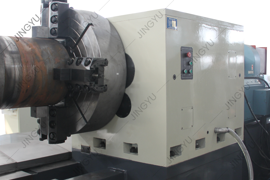 CK84100 and CK84125 CNC Roll Lathe for Variable-Diameter JobsThis roll lathe family uses a reinforced guideway and rigid tool holder to sustain heavy cutting torque, making it suitable for the multi-pass variable-diameter turning discussed above where consistent surface speed and tool stability are critical.View Product →
Milling parameters follow the same procedure, but chip thinning matters more when radial engagement is low. If a 40 mm end mill takes a 4 mm radial pass, the chip produced is thinner than the programmed feed per tooth. Keeping a normal feed per tooth causes rubbing and rapid cutter wear. In that situation, increase feed per tooth or use a larger stepover.
For crescent grooves and contoured rib grooves on steel rolls, indexable carbide cutters typically run at 30–90 m/min depending on hardness. Pre-hardened rolls at 45–55 HRC use the lower end; softer plain-carbon steel uses the higher end. A heavy-duty CNC roll milling machine provides the rigidity needed to keep these feeds stable and the cutter engaged without chatter.
Every calculated speed and feed assumes a rigid machine, proper clamping, and short tool overhang. The moment chatter starts, the parameters from the chart are no longer valid. When we see vibration marks, the first step is to reduce depth of cut, not feed rate. Lower depth reduces cutting force and removes the unstable dynamic condition. Then adjust spindle speed about 10–20% to move away from the resonant range. Feed should stay near the target chip load, because a too-low feed can worsen rubbing and heat.
Long shaft work, typical in roll turning and grinding, needs stable support from centers and steady rests. The same principle applies on a CNC reinforced milling machine: a heavy base, wide guideways, and good damping allow higher feed rates and more consistent tool life. If the same operation runs on a lightweight machine, reduce the calculated speed to about 60–70% of the original value. Practical experience with high-speed vibration in grinding and machining can save hours of troubleshooting; see our note on dealing with CNC grinder vibration at high speed.
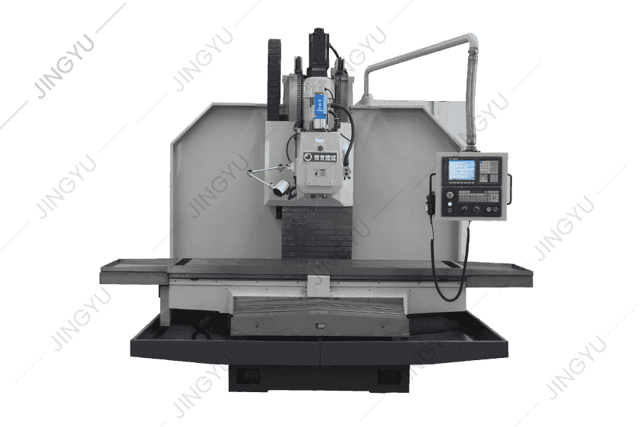 XKV1800 CNC Vertical Reinforced Milling Machine for Stable Heavy CutsWith a heavy base, wide guideways, and large work envelope, this vertical mill offers the rigidity and damping that the preceding paragraph links to higher feed rates and longer tool life, useful for long shaft and roll work.View Product →
A feed-and-speed table is only a starting line. The best numbers come from your own machine, tool holder, workpiece batch, and coolant condition. After each trial cut, record the spindle load, surface finish, chip color, and tool wear pattern. Then make one change at a time. This methodical loop is more valuable than any shortcut.
For operators working on roller turning, roll grinding, or profile milling, reliable output depends equally on calculation and on the stiffness of the machine. Machine design, not just programming, decides how aggressive you can safely be. You can review our heavy-duty machine philosophy by starting with our CNC machine tool manufacturing approach.
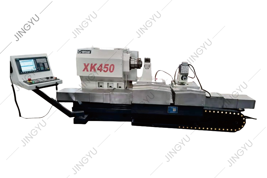
We have accumulated rich experience in the processing and use of rebar rolls, and have conducted in-depth analysis and research on the technology of s...
See Details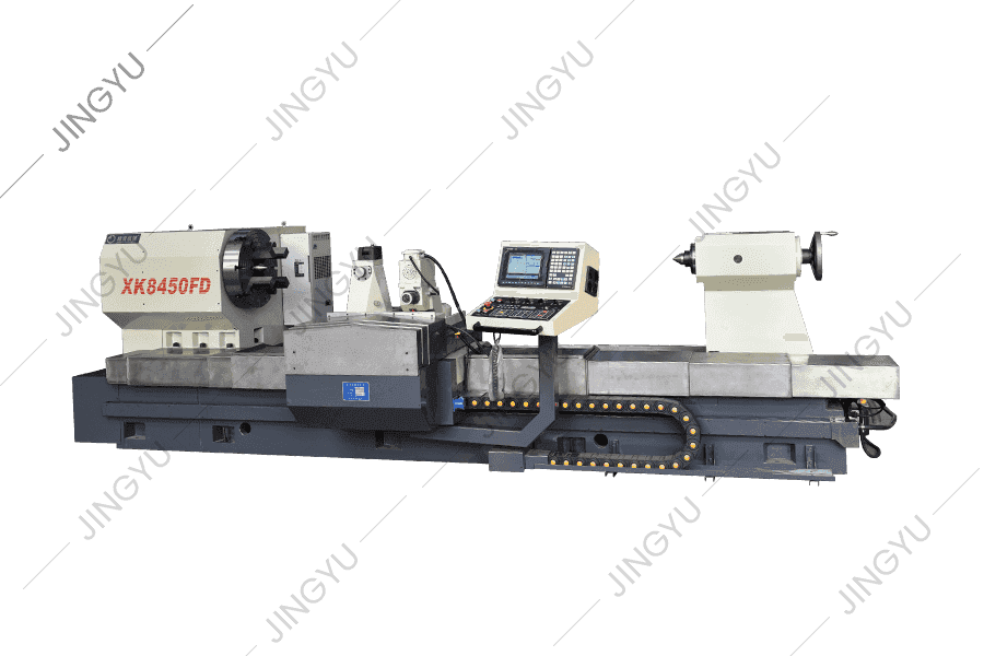
In view of the problems of high speed steel roll processing, XK8450 CNC roll milling machine is a new type of CNC roll groove processing machine tool ...
See Details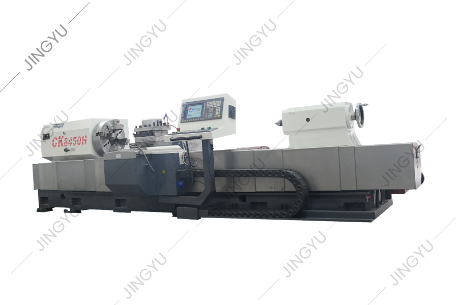
This series of machine tools is mainly used to pass and process rolls. It can also turn the outer circle and roll neck of rolls, and can also turn par...
See Details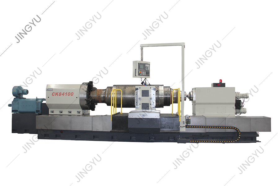
CK84 series CNC roll lathe adopts Siemens 828D CNC system and is driven by a servo motor. When designing this machine tool, we fully analyzed the tech...
See Details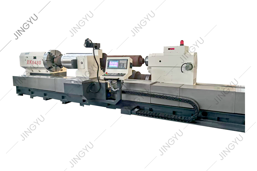
At present, pattern roll engraving at home and abroad generally adopts electrolysis method, ordinary horizontal milling machine milling and other proc...
See Details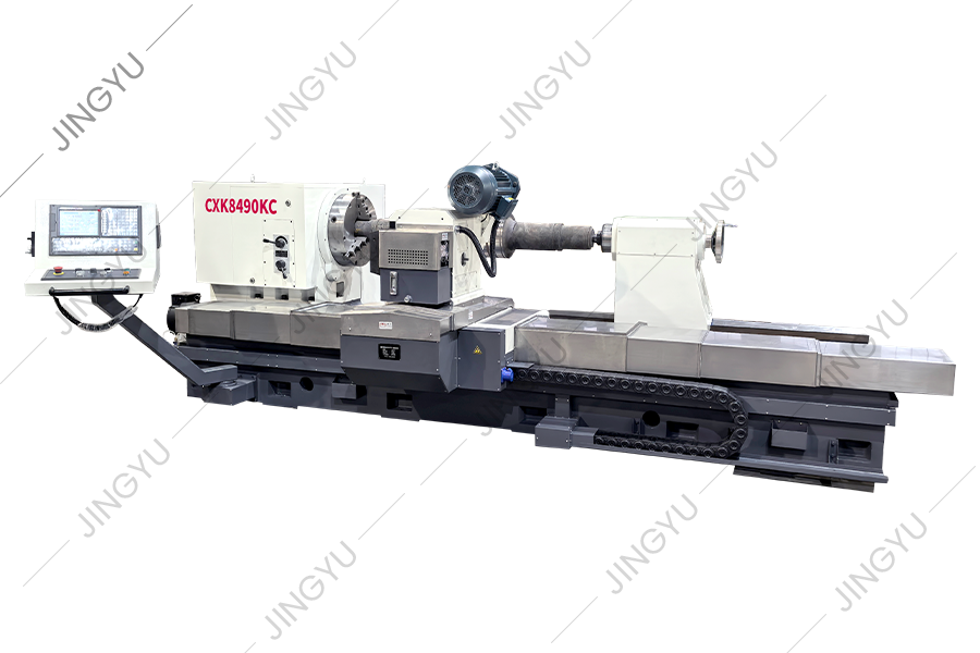
This machine tool is a new type of CNC roll grooving machine tool developed based on the company's CNC roll milling machine series and after full rese...
See Details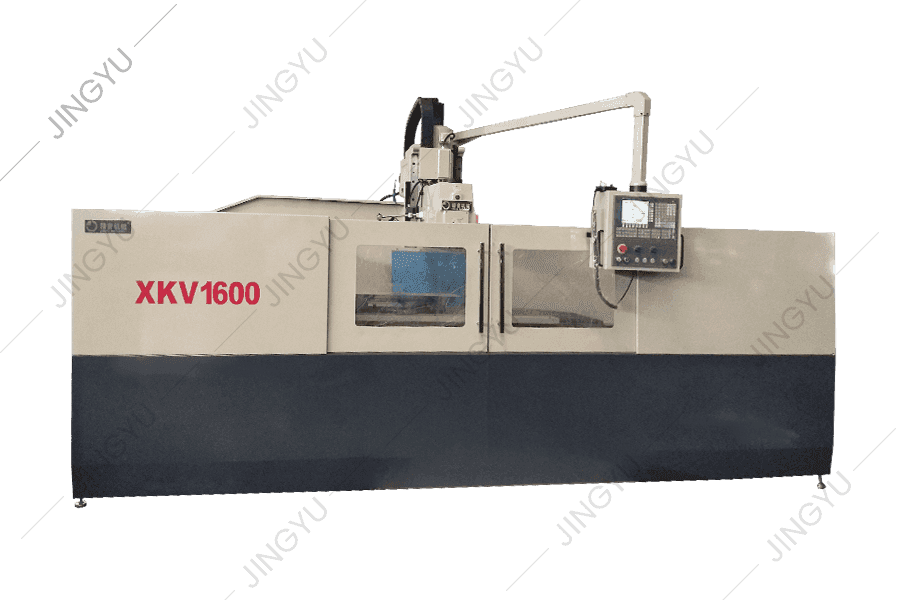
The CNC-reinforced milling machine adopts a full-gear spindle box, and the spindle transmission part adopts gears with precision of more than 6 levels...
See Details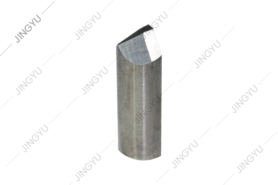
This series is mainly for CNC crescent groove milling machines to provide common-wearing parts, such as milling tool holders, milling cutters, support...
See Details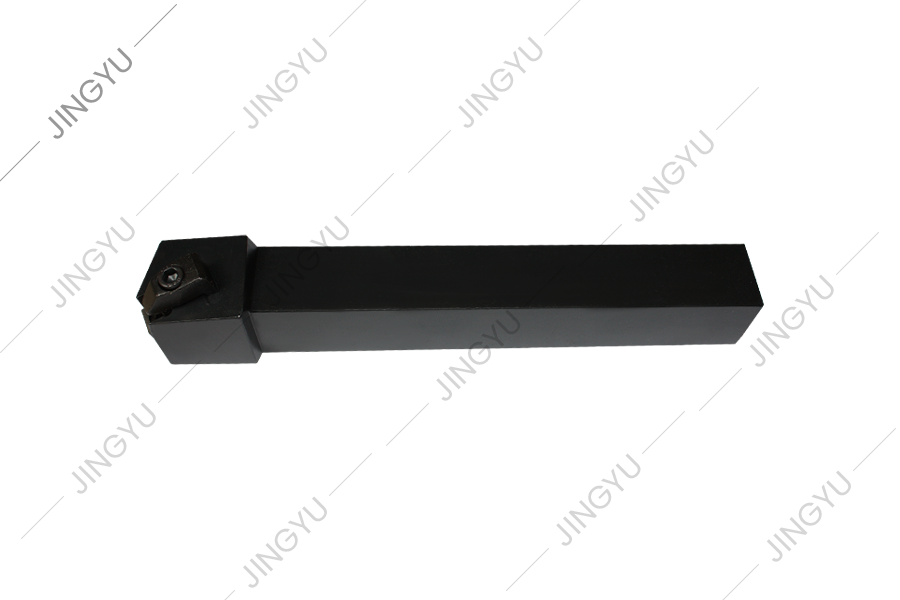
This series mainly provides common-wearing parts for CNC roll lathes, such as CBN blades, PCD blades, chucks, screws, etc.
See Details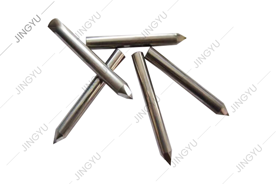
We also supply other spare parts, such as checkered plate milling cutters, roll slotting tools, oil pumps, motors, CNC systems, etc.
See DetailsNo.3, Xinghe Road, Zhaxi Industrial Park, Chongchuan District, Nantong, Jiangsu Province, 226003, P.R.China
info@rolllathe.com jennifergao@rolllathe.com
+86-513-85636116
Copyright © Nantong Jingyu Machinery Co., Ltd. All Rights Reserved
 China Roll Turning Lathe Manufacturers
